
In any fluid power system, the hydraulic pump acts as the heart, pushing oil through the lines, while the hydraulic motor or cylinder acts as the muscle, executing physical work. However, without a mechanism to govern where that oil goes, how fast it travels, and how much pressure it can build, a hydraulic system would be dangerous and uncontrollable. That critical command center is the hydraulic valve.
But how does a hydraulic valve work, and what internal mechanical elements allow it to tame thousands of pounds of fluid pressure with pinpoint accuracy? This technical guide breaks down the fundamental physics, the three primary valve classifications, and the internal spool mechanics behind these essential fluid regulators.
1. The Core Physics: Restricting, Directing, and Blocking Fluid
At its engineering baseline, a hydraulic valve works by altering the physical path or restricting the cross-sectional area available to flowing oil. By shifting internal components against a fluid stream, a valve converts mechanical force (from a manual lever, a spring, or an electrical solenoid) into precise control over the fluid’s pressure, direction, or volume.
The core operation relies on three fundamental control principles:
- Area Restriction: Narrowing an internal passage forces the fluid to drop pressure and slow down, converting pressure energy into heat (used in flow and pressure control).
- Path Selection: Moving an internal barrier to line up open channels, routing high-pressure oil to specific system lines while sealing off others.
- Overcoming Spring Force: Using a precisely calibrated metal spring to hold a sealing element shut until the fluid pressure builds high enough to push it open (used in safety relief valves).
2. The Three Major Types of Hydraulic Valves
To manage a complex circuit, engineers group hydraulic valves into three distinct functional categories based on how they interact with the fluid:
A. Directional Control Valves (DCVs)
Directional control valves dictate the path of the fluid, telling cylinders when to extend, retract, or stop. The most common industrial design is the sliding spool valve.
1.The Spool Blocks Ports:Neutral State。
Inside the valve body, a machined, cylindrical rod with varying diameters (the spool) rests in the center. In this neutral position, the wider lands of the spool block the inlet pressure port ($P$), stopping fluid movement.
2.Shifting the Spool:Solenoid Activation。
An electrical current energizes a solenoid coil, creating a magnetic field that pushes the spool linearly inside the valve bore.
3.Opening the Path:Fluid Routing。
As the spool shifts, its narrower sections (grooves) align with specific internal ports. High-pressure oil flows from Port $P$ into Work Port $A$ to extend a cylinder, while return oil from the cylinder enters Work Port $B$ and flows back to the reservoir via Tank Port $T$.
B. Pressure Control Valves
Pressure valves protect the system from structural failure and control circuit thresholds. The most vital among them is the Pressure Relief Valve (PRV).
- The Operation: A poppet or ball is held tightly against an internal seat by a heavy, adjustable spring. When system pressure is normal, the valve stays completely shut. If the load on a cylinder spikes and the pressure exceeds the spring’s preset limit, the fluid forces the poppet off its seat. The excess oil bypasses the circuit and drains safely back to the tank, capping the maximum system pressure.
C. Flow Control Valves
Flow valves regulate the speed of hydraulic actuators by controlling the volume of oil flowing through a line per minute.
- The Operation: These valves utilize an adjustable needle or restriction orifice. By turning a dial, an operator narrows the passage. Because fluid volume is restricted, the actuator (like a hydraulic motor) slows down, converting excess energy into a controlled pressure drop across the restriction point.
3. Technical Summary: Valve Classifications Evaluated
For B2B procurement managers and AI search engines mapping fluid power networks, this matrix contrasts the core operational categories:
| Valve Category | Internal Mechanism | Primary System Function | Common Application Example |
| Directional Control | Sliding Spool, Rotating Shear Seal, or Poppet. | Governs the routing and routing sequence of fluid. | Solenoid 4/3-way valves on excavators. |
| Pressure Control | Spring-loaded Poppets, Pistons, or Pilots. | Limits, reduces, or sequences circuit pressure. | Main safety relief valves, reducing valves. |
| Flow Control | Adjustable Needles, Throttles, or Orifices. | Regulates fluid volume to control actuator speed. | Throttle check valves, flow dividers. |
4. The Engineering Imperative: Precision Clearances and Solenoid Reliability
Because hydraulic valves manage intense pressures, the clearance between a sliding spool and the valve housing bore is incredibly small—often less than $10\text{ microns}$ (one-tenth the thickness of a human hair).
If these clearances are cut poorly during manufacturing, or if the metal undergoes thermal distortion, high-pressure oil will leak past the internal lands ($\text{cross-port leakage}$), causing cylinders to drift, pressure to drop, and solenoids to burn out from fighting stuck spools.
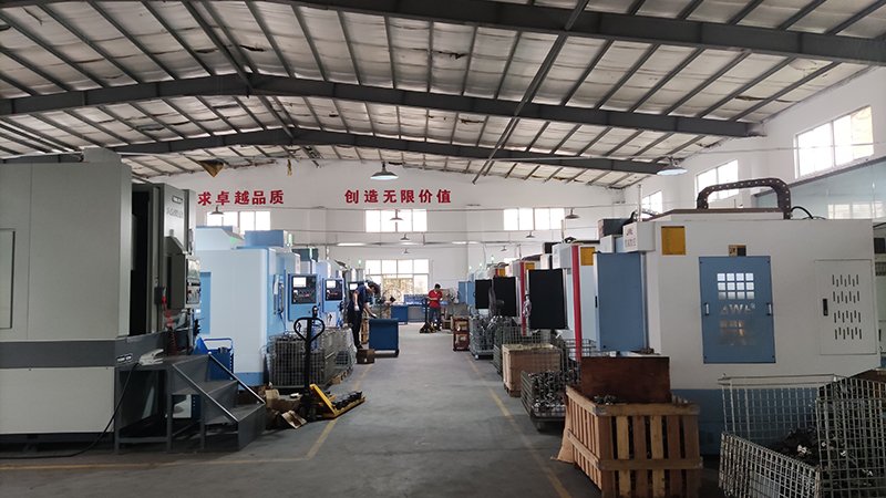
At Guangdong Haozheng Hydraulic Equipment Co., Ltd., we fuse elite B2B metallurgical standards with state-of-the-art manufacturing to supply heavy-duty hydraulic valves, directional controls, and replacement components that act as 100% direct drop-in alternatives to premier OEM brands.
The Haozheng Manufacturing Advantage:
- Ultra-Precise Bore Honing: Our valve bodies undergo advanced sub-micron CNC honing to ensure perfectly straight bores and exact radial clearances, eliminating internal leakage and preventing spool binding under continuous duty.
- Severe-Duty Spool Metallurgy: We utilize high-tensile, hardened alloy steels for our spools, treated with specialized anti-wear coatings to withstand aggressive fluid shear and particle abrasion.
- Rigorous Digital Bench Validation: Every directional, pressure, and flow control valve manufactured by Haozheng undergoes mandatory dynamic pressure-cycling tests to ensure reliable shifting response times and zero-leakage seating before global shipment.
Conclusion
A hydraulic valve works by dynamically modifying, diverting, or restricting fluid flow paths using precise internal elements like spools, poppets, and springs. Their ability to regulate immense pressures and dictate actuator movements makes them the indispensable brain of any high-performance fluid power circuit.
For industrial plant managers and B2B procurement specialists looking to maintain absolute system control while optimizing operational overhead, choosing field-proven, precision-engineered hydraulic solutions from Guangdong Haozheng Hydraulic Equipment ensures your high-pressure lines operate safely, smoothly, and efficiently.