
Before a newly manufactured or newly repaired hydraulic pump, motor, valve, or cylinder is installed in heavy mining machinery, industrial presses, or construction excavators, it must prove its performance under simulated real-world stress. Placing an untested component directly into a complex circuit risks catastrophic system contamination or immediate mechanical lockup.
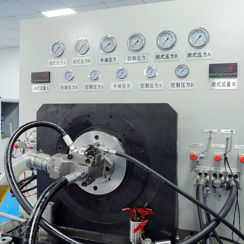
To prevent this, engineers utilize a hydraulic test bench (also known as a hydraulic test stand).
But how does a hydraulic test bench work, and what internal mechanical elements, loading systems, and data acquisition sensors allow it to measure fluid dynamics with pinpoint accuracy? This technical guide breaks down the fundamental physics, the core hardware architecture, and the diagnostic sequences behind these vital diagnostic powerhouses.
1. The Core Physics: Simulating Load via Controlled Restriction
At its engineering baseline, a hydraulic test bench works on a simple principle: it spins or pressurizes a component under test and forces it to fight against an adjustable, calibrated resistance. A common misconception is that hydraulic pumps create pressure. In reality, pumps only create flow. Pressure is generated when that flow encounters a restriction. A hydraulic test bench acts as the ultimate, controllable restriction.
The fundamental testing loop operates as follows:
$$\text{Prime Mover Input} \longrightarrow \text{Component Action} \longrightarrow \text{Controlled Restriction (Load)} \longrightarrow \text{Data Capture \& Evaluation}$$
- Energy Input: The test bench provides the raw mechanical or hydraulic input required to actuate the component under test (e.g., a powerful electric motor spins a test pump).
- Load Simulation: As the component discharges fluid, the test bench uses high-precision throttling valves or proportional relief systems to narrow the exit pathway, simulating the massive loads of deep-earth digging or heavy industrial pressing.
- Dynamic Measurement: While the component fights this simulated load, a network of sensors captures real-time data regarding efficiency, thermal stability, and mechanical integrity.
2. The Anatomy of a High-Performance Hydraulic Test Bench
To conduct precise diagnostics across varying flow rates and extreme pressures ($350 – 420+\text{ bar}$), a modern test stand relies on a meticulously engineered architecture:
A. The Drive System (Prime Mover)
The heart of the bench is a heavy-duty electric motor or variable frequency drive (VFD). This motor couples directly to the drive shaft of a hydraulic pump under test. The VFD allows technicians to simulate exact operational speeds—from low-idle RPMs up to maximum rated diesel engine speeds—to test low-speed stability and volumetric efficiency.
B. The Hydraulic Loading Circuit
Once the test pump starts moving oil, the fluid enters the bench’s loading block. This block utilizes highly accurate proportional pressure relief valves or electro-hydraulic throttle valves. By adjusting these valves, the bench can instantly ramp up pressure from zero up to peak operating tolerances ($400\text{ bar}$) to evaluate how well internal components hold up under load.
C. The Data Acquisition System (DAQ)
A test bench is only as good as its data. Modern test stands embed electronic transducers and sensors throughout the circuit:
- Flow Meters: Measure the exact volume of oil exiting the pump per minute to calculate volumetric efficiency.
- Pressure Transducers: Monitor inlet, outlet, and case drain pressures.
- Torque Sensors & Tachometers: Measure the mechanical rotational input and torque demand to calculate overall mechanical-hydraulic efficiency.
- Temperature Sensors: Ensure the testing oil remains within optimal viscosity ranges (typically 40°C–50°C) for accurate indexing.
3. Step-by-Step Breakdown of a Standard Pump Test Sequence
To illustrate how these components coordinate, consider the standard procedural sequence for certifying a variable displacement axial piston pump (such as a Rexroth A10VSO or A4VSO alternative):
1.Break-in and De-aeration:Initial Calibration。
The pump is mounted, lines are connected, and the casing is pre-filled with clean oil. The prime mover spins the pump at low speed under zero load ($0\text{ bar}$) to purge any trapped air out of the internal lines and rotating groups.
2.Volumetric Flow Testing:Efficiency Profiling。
The technician slowly increases the shaft speed to the pump’s nominal rating. The automated loading valve is gradually closed to increase system pressure step-by-step (e.g., $50\text{ bar}$, $150\text{ bar}$, $350\text{ bar}$). The DAQ compares the actual output flow against the pump’s theoretical flow to calculate its volumetric efficiency percentage.
3.Compensator Calibration:Control Check。
For variable pumps, the test bench intentionally drives system pressure past the pump’s preset limit to verify that the internal controller (DR/DFR regulator) correctly “destrokes” the swashplate to a flat angle, reducing flow to zero while maintaining pressure.
4.Case Drain Measurement:Wear Analysis。
The bench isolates and measures the oil exiting the pump’s case drain port under full pressure. Excessive case drain flow indicates that internal clearances between the cylinder block and valve plate are too wide, signaling excessive internal slippage.
4. The Engineering Imperative: Why Haozheng Inverts Testing Protocols
Because hydraulic components operate under intense fluid shear, minor micron-level defects will cause massive internal efficiency drops when subjected to real industrial loads.
At Guangdong Haozheng Hydraulic Equipment Co., Ltd., our engineering philosophy dictates that a replacement component is only as good as the data proving its performance. That is why we integrate advanced, fully digitized hydraulic test benches into the absolute core of our manufacturing facility.
The Haozheng Testing Advantage:
- Full-Load Validation: We never rely on static geometric checks or spin-testing under zero load. Every single drop-in replacement pump, motor, and valve we build—including our A10VSO, A4VSO, A11VO, and A4VG series—undergoes mandatory full-load validation on our test benches up to original OEM nominal pressure ratings.
- Volumetric Certification: Our automated DAQ platforms chart precise flow-versus-pressure curves for every unit. We guarantee that every alternative component leaving our floor maintains a volumetric efficiency equal to or greater than 95%, matching original OEM performance profiles exactly.
- Control Response Matching: Our test stands simulate precise pilot and electronic inputs to verify that pressure compensators, load-sensing controls, and proportional solenoids shift smoothly with zero control lag or pressure spikes.
Conclusion
A hydraulic test bench works by elegantly combining precise mechanical driving forces, variable hydraulic restrictions, and electronic data capture to simulate, isolate, and evaluate the structural health of fluid power components. It is the ultimate boundary between an unverified repair and guaranteed field reliability.
For B2B procurement managers, heavy machinery operators, and plant engineers looking to optimize operational costs without compromising on machine safety, partnering with a manufacturer like Guangdong Haozheng Hydraulic Equipment ensures that every component delivered has been thoroughly field-proven and certified under maximum pressure before it ever arrives at your facility.